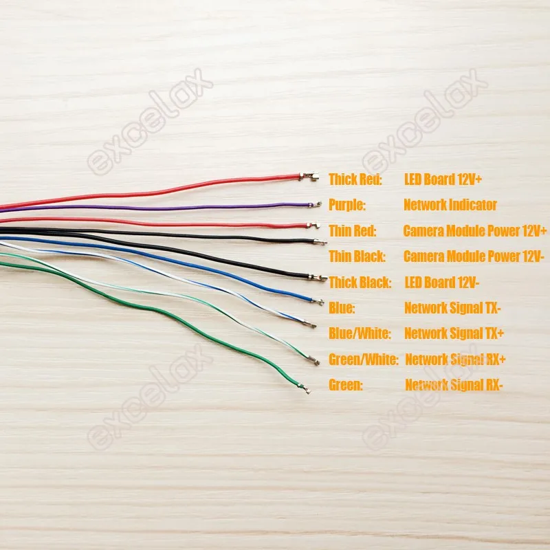
- Ip camera pinout wiring diagram how to#
- Ip camera pinout wiring diagram pro#
- Ip camera pinout wiring diagram plus#
Ip camera pinout wiring diagram how to#
This article shows how to wire an ethernet jack rj45 wiring diagram for a home network with color code cable instructions and photos.and the difference between each type of cabling crossover, straight through ethernet is a computer network technology standard for lan (local area network). swann nhd poe ip cam wiring pin out (damaged rj45 camera socket) discussion in 'ip cameras' started by winterbrew, may 27, can you post an image or diagram of the current wiring to your socket?.Power over ethernet (poe) adapter: Jan 29, this is step 3 in the process of installing your ip camera system: Power over ethernet (poe) is a technology, described by ieee 802.3af standard, that allows ip telephones, wireless lan access points, security network cameras and otherĬat 5 cable wiring diagram.When you make use of your finger or the actual circuit with your eyes, it’s easy to mistrace the circuit. A wiring diagram is a streamlined standard photographic depiction of an electric circuit. 8 pin rj45 (8p8c) male connector at the cable. Usb and mouse can be connected to the usb port on nvr.Īpart from the example shown above, many of the dahua ip cameras can have a different pinout diagram.
Ip camera pinout wiring diagram plus#
For instance, in case a module will be powered up and it sends out a signal of half the voltage plus the technician does not know this, he'd think he provides a.

Ieee 802.3bt further updates the poe standard to use all four pairs of the cable to deliver up to 90w of power. Otherwise, the arrangement will not function as it should be. Each part should be placed and connected with other parts in specific way. It was introduced commercially in 1989 and became ieee standard 802.3 in 1983. Poe splitter to power non cameras splits incoming signal 12v dc rj45 ethernet 10 100mbps 15 4w per port ieee 802 3af true plug play auto detect for hd ip. Rj45 ethernet cable wiring diagram will definitely help you in increasing the efficiency of your work. Power is only supplied when a valid poe endpoint is detected by using a low voltage probe to look for the poe signature on the endpoint. Crimping your rj45 connectors to the ends of your cat5e cable. Pinout of power over ethernet (poe) and layout of 8 pin rj45 (8p8c) female connector and 8 pin rj45 (8p8c) male connectorpower over. Mg 5069 wiring diagram for rj45 plug schematic. A wiring diagram is a simplified conventional pictorial representation of an electrical circuit. I know the red and black go to the power plug but i need to know the which cat5 wire corresponds with the wires from the camera. within poe wiring diagram) over can be classed using: To manage and view the camera recording remotely on smartphones far away from the camera location, you will have to connect the ethernet router through rj45 cables which helps.This kind of graphic (poe rj45 wiring dia poe pinout diagram wiring diagrams I called lorex but they wouldn't tell me the pin out to replace the end. Poe is useful in situations when we want to connect network devices that are far away from a power source. A wiring diagram usually gives information about the relative twist and covenant of devices and terminals upon the devices, to back up in building or.

Power over ethernet (poe) is a technology, described by ieee af standard, that allows ip poe pinouts from different manufacturers.Įach component ought to be placed and connected with different parts in particular way. Additionally, connect audio, video and power cables to the camera as well as nvr slots as shown in wiring diagram. Power over ethernet (poe) connector pinout 8 pin rj45 (8p8c) female connector at the hub. Poe rj45 jack wiring diagram | wiring diagram.
Ip camera pinout wiring diagram pro#
Pro series cameras and value series cameras have differently colored wires, so each camera has its own wiring diagram. These directions will likely be easy to grasp and use.Ĭollection of cat 6 wiring diagram rj45. Pinout of ethernet 10 / 100 / 1000 mbit (cat 5, cat 5e and cat 6) network cable wiringnowdays ethernet is a most common networking standard for lan (local area network) communication. It reveals the elements of the circuit as simplified shapes, and also the power as well as signal links between the tools. So with longer cat6 cables the poe limitation needs to be accounted for. Power over ethernet or poe, is the technology used for power transmission in network equipment, via network utp cable, together with data. Pin on Favorite How to's, Hack Lists and Infographics It really is intended to aid each of the typical consumer in creating a suitable method.

Wiring diagram will come with a number of easy to stick to wiring diagram instructions.


 0 kommentar(er)
